As to the first method, I have made two, but the circuit is a little difficult and the components is not easy to get on hand, which is difficult for the electronic beginner.
The second method is comparatively simply, but has a obvious weakness, i.e. the bandwidth is narrow. A typical work made by a American guy, (see http://www.serasidis.gr/circuits/AVR_oscilloscope/avr_oscilloscope.htm), has a 7.7KHz bandwidth. And some people made it with AVR and STC, but also their bandwidth does not exceed 10KHz.
Recently I have seen a guy using Arduino to build digital oscilloscope, which is even more simple than the second method. But still doesn't work well with narrow bandwidth. Therefore I want to have a try to see if there is better way to solve this problem. After making and testing, and modifying codes constantly, I can now improve the sampling frequency and make a big progress.
The specification of the final work is as follow:
response frequency: 10-50 KHz,
Power Supply: 5V
LCD: 128*64
Measuring Display Zone: 96X64
Message Display Zone: 32X64, indicates the frequency and Vpp,etc.
SYNC Method: Rising along the trigger
Scan Speed: 0.02ms/div 10ms/ div, 9 grades according to 1-2-5
Hold Function: hold displaying wave and parameters
STEP 1 PROTOTYPE TESTING
The best advantage for arduino is its abundant resources, and you need not to know much thing about microcontroller. I make use of the library of LCD: u8glib.h, which makes programming very easy, otherwise to drive LCD will waste you a lot of time.
Below is my test circuit with Arduino UNO, and 12864 LCD controlled by ST7920.

Now input all this codes and compile them, the oscilloscope starts working. Isn't is easy?
- #include <U8glib.h> //声明库
- U8GLIB_ST7920_128X64_4X u8g(13, 12, 11); // 声明液晶屏 SPI Com: SCK =13, MOSI = 12, CS = 11
- int x,y; //绘点坐标
- int Buffer[128]; //缓存值储存数组
- void setup( ) { }
- //采样
- void sample( )
- {
- for(x = 0;x < 128;x++)
- Buffer[x] = analogRead(A0); //信号采样
- for(x = 0;x < 128;x++)
- Buffer[x] = 63-(Buffer[x]>>4); //计算纵坐标值
- }
- //显示
- void draw( )
- {
- for(x = 0;x < 127;x++)
- u8g.drawLine(x,Buffer[x],x,Buffer[x+1]); //画相邻两点连线
- u8g.drawLine(64,0,64,63); // 画坐标轴
- u8g.drawLine(0,32,128,32);
- for(x=0;x<128;x+=8) //画坐标轴刻度
- u8g.drawLine(x,31,x,33);
- for(x=0;x<64;x+=8)
- u8g.drawLine(63,x,65,x);
- u8g.drawFrame(0,0,128,64); //画边框
- }
- void loop( )
- {
- sample(); //采样
- u8g.firstPage(); //清屏
- do draw( ); //显示
- while( u8g.nextPage( ));
- }


With this prototype circuit, I measured one ADT time for Arduino is about 111ms using analogyread() function, which is very slow, meaning the bandwith is only 1KHz. So the next step is to raise the AD transition speed.
STEP 2 Building Complete Machine
When I performed the experiment , I use Arduino UNO, Now I replace it with Arduino Pro mini so that I can make the volume small.
Circuit:

Components list:
Arduino PRO mini
LCD 12864
Capacitor: 100μF 25V
Potentiometer: 50K
Peg Board
Button Switch
Power Switch
Battery holder
Main Case
1. Solder Arduino PRO mini


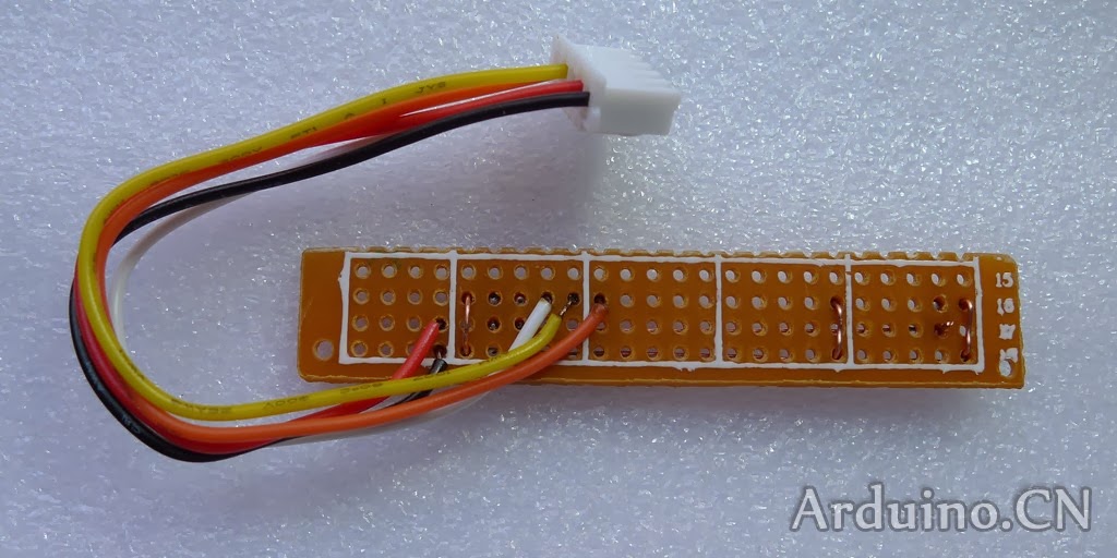
2. Solder Peg board


3. Make LCD Peg board

4.Assemble circuit board


5. Make main case

6.Total assembly


STEP 3 downloading codes and testing


Hi, I'd love to build your oscilloscope, but since
回复删除I am totally new to ArduinoI would be glad if you will send me
all code.
I've tried the first code, it works fine, but now would
I like to do the whole scope.
oz2hns@gmail.com
sincerely,
Hans Otto Nielsen
Hey. I would also be interested in the complete code. I have already bought and Arduino Pro Mini :-). Thank you. Sincerely Tono. My address is tony5@centrum.sk
回复删除此评论已被作者删除。
回复删除Hi , great project, can you tell me how did you control the time / div ?? please , send the code to my email champx012@gmail.com
回复删除Hi, this is great project. I would also be interested about complete code. Can you share it? My address is: pollakstevo@gmail.com. Regards Stefan
回复删除Thanks great proyects, please do you send me code?
回复删除lightcalamar@gmail.com
Hi. Can i have the code and i also, please? Thank you
回复删除stratos_cha@yahoo.com
Nobody, has taken the new firmware;
回复删除