

written by Josehf Murchison
I have a number of oscilloscopes; the only one I didn’t build or rebuild is my DSO Nano oscilloscope. The vacuum tube oscilloscopes were weeklong projects unlike the DSO 062 oscilloscope that took only two hours to assemble. This is my second DSO 062 LCD Oscilloscope my other one managed to grow legs and go on a trip without me. I purchased the kit from China www.aliexpress.com for $40, it is very cheap in China as tremendous electronic gadgets are manufactured there.
Since the Assembly Notes have step by step instructions on how to assemble the scope most of this Instructable will be on the things not in the Assembly Notes. And little tricks I learned through the years working in electronics
Step 1: The Kit


When your DSO 062 Oscilloscope arrives in the mail open it, inside you will find several packages of parts and two pieces of paper marked, “General Assembly Guide and 062 Oscilloscope Quick Reference”. Put everything back in the box but the paper marked “062 Oscilloscope Quick Reference”.
Take the quick reference to your computer, on the bottom of the quick reference it says “For Complete and updated documents please visit: http://www.jyetech.com that is JYETECH.
On your computer go to:
http://www.jyetech.com
Click on English
Under Quick Links Click on Documents
Down load all the files under models 06203P, 06203KP, and 06204KP for all three models it is the same files.
Quick Reference
Operating Instructions
Assembly Notes
Troubleshooting Guide
Assembly Back
Assembly Front
How to Upgrade Firmware by Bootloader
How to Program 062 Oscilloscopes
Part list
Schematic
Step 2: Print Files


Print the pdf files:
Assembly Notes
Troubleshooting Guide
Assembly Front
Assembly Back
Part list
Operating Instructions
The reason for printing the pdf files is so you can tick off the steppes as you follow the assembly notes.
Assembly Notes
Troubleshooting Guide
Assembly Front
Assembly Back
Part list
Operating Instructions
The reason for printing the pdf files is so you can tick off the steppes as you follow the assembly notes.
Step 3: Check the Parts
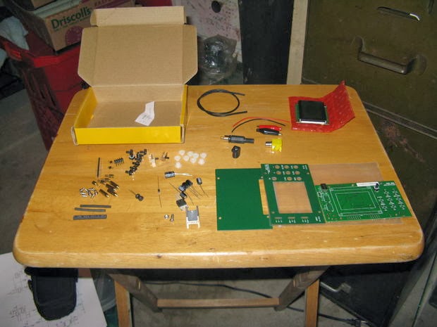


From the printed pdf files check the parts make sure all the parts are in the kit and check them to be sure they fit the circuit board. Whether deliberately or by accident it is not uncommon for parts to be substituted in kits, so make sure they are the right parts and they fit before you start to assemble your oscilloscope.
Step 4: Tools

Step 5: Assembling the Oscilloscope


Step 6: Testing
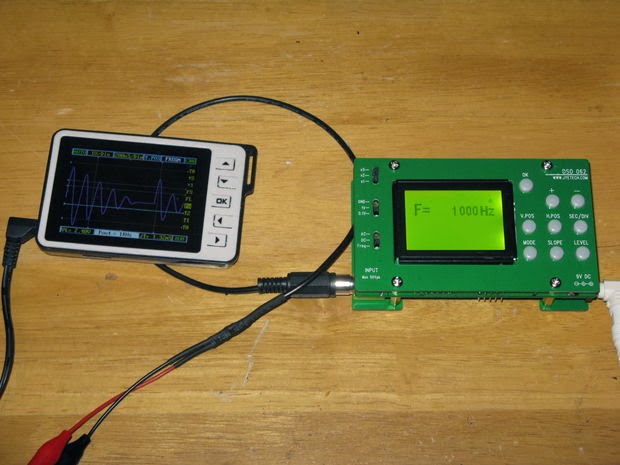
After assembling the circuit board completely you need to test the oscilloscope before putting the front and back plates on. Connect the power to the oscilloscope. The LCD should light up. “Boot loader” then should come on the LCD. The LCD should switch to WWW.JYETECH.COM. Last F= and Hz This indicates the oscilloscope is functioning normally, if it doesn’t display this on the LCD follow the Troubleshooting Guide.


Step 7: Assembling the Probe


Step 8: The BNC Connector


Step 9: Testing the Probe and Oscilloscope


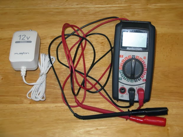
Step 10: Making a Portable Power Supply


All the parts for this I got at my local Radio Shack the Source here in Canada. 8 AA batteries 1 9 volt battery terminal 1 coaxial power plug 1 12 volt AA battery holder Shrink tube Slip the shrink tube over the wires of the 9 volt battery terminal and heat to shrink. Unscrew the collar of the coaxial power plug and slip it over the wire of the 9 volt battery terminal. Then solder the red wire to the center tab of the coaxial cable connector and the black wire to the outer tab and screw the collar back in place. Place the 8 AA batteries in the battery holder, clip the 9 volt battery terminal to the holder, and plug it into the oscilloscope and watch it boot up.
Step 11: And We Are Done

没有评论:
发表评论