显示标签为“diy”的博文。显示所有博文

2014年1月19日星期日

Digital Oscilloscope based on Arduion

We often see someone making a digital oscilloscope on the net. The digital oscilloscope generally has a module of A/D transtion, and there are two kinds of circuit according to the method of A/D transtion: 1. Special ADC chip with mircocontroller, 2.making use of the interal ADC function.
 As to the first method, I have made two, but the circuit is a little difficult and the components is not easy to get on hand, which is difficult for the electronic beginner.
The second method is comparatively simply, but has a obvious  weakness,  i.e. the bandwidth is narrow. A typical work made by a American guy, (see http://www.serasidis.gr/circuits/AVR_oscilloscope/avr_oscilloscope.htm), has a 7.7KHz bandwidth. And some people made it with AVR and STC, but also their bandwidth does not exceed 10KHz.

  Recently I have seen a guy using Arduino to build digital oscilloscope, which is even more simple than the second method. But still doesn't work well with narrow bandwidth. Therefore I want to have a try to see if there is better way to solve this problem. After making and testing, and modifying codes constantly, I can now improve the sampling frequency and make a big progress.
  The specification of the final work is as follow:
  response frequency: 10-50 KHz,
  Power Supply: 5V
  LCD: 128*64
  Measuring Display Zone: 96X64
  Message Display Zone: 32X64, indicates the frequency and Vpp,etc.
  SYNC Method:   Rising along the trigger
  Scan Speed: 0.02ms/div 10ms/ div, 9 grades according to 1-2-5
  Hold Function:  hold displaying wave and parameters


STEP 1 PROTOTYPE TESTING


 The best advantage for arduino is its abundant resources, and you need not to know much thing about microcontroller. I make use of the library of LCD: u8glib.h, which makes programming very easy, otherwise to drive LCD will waste you a lot of time.

  Below is my test circuit with Arduino UNO, and 12864 LCD controlled by ST7920.


Now input all this codes and compile them, the oscilloscope starts working. Isn't is easy?


      #include <U8glib.h> //声明库
       U8GLIB_ST7920_128X64_4X u8g(13, 12, 11); // 声明液晶屏 SPI Com: SCK =13, MOSI = 12, CS =  11
       int x,y; //绘点坐标
       int Buffer[128]; //缓存值储存数组
       void setup( ) {  } 
       //采样
       void sample( )  
      {  
       for(x = 0;x < 128;x++) 
         Buffer[x] = analogRead(A0);  //信号采样
       for(x = 0;x < 128;x++)  
         Buffer[x] = 63-(Buffer[x]>>4); //计算纵坐标值
      }
      //显示
      void draw( )  
      {  
        for(x = 0;x < 127;x++)  
           u8g.drawLine(x,Buffer[x],x,Buffer[x+1]);  //画相邻两点连线  
       u8g.drawLine(64,0,64,63); // 画坐标轴 
       u8g.drawLine(0,32,128,32);
       for(x=0;x<128;x+=8)   //画坐标轴刻度 
         u8g.drawLine(x,31,x,33);
       for(x=0;x<64;x+=8)
         u8g.drawLine(63,x,65,x);
       u8g.drawFrame(0,0,128,64); //画边框 
      }   
      void loop( ) 
       { 
         sample();         //采样
         u8g.firstPage();  //清屏
         do  draw( );      //显示
         while( u8g.nextPage( ));
       } 

With this prototype circuit, I measured one ADT time for Arduino is about 111ms using analogyread() function, which is very slow, meaning the bandwith is only 1KHz. So the next step is to raise the AD transition speed.

STEP 2  Building Complete Machine


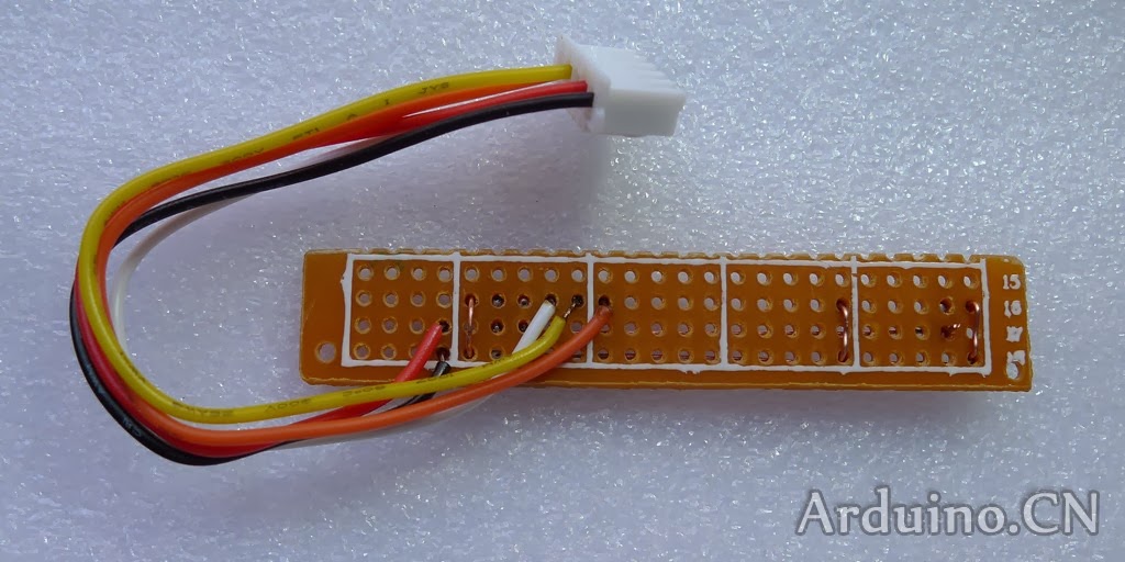
  When I performed the experiment , I use Arduino UNO, Now I replace it with Arduino Pro mini so that I can make the volume small.
   Circuit:


Components list:

 Arduino PRO mini
 LCD 12864
 Capacitor: 100μF  25V
 Potentiometer: 50K
 Peg Board
 Button Switch
 Power Switch
 Battery holder
 Main Case

1. Solder Arduino PRO mini


2. Solder Peg board


3. Make LCD Peg board


4.Assemble circuit board


5. Make main case


6.Total assembly


STEP 3  downloading codes and testing


2014年1月18日星期六

Building a Digital Oscilloscope from a DIY Kit


written by Josehf Murchison

I have a number of oscilloscopes; the only one I didn’t build or rebuild is my DSO Nano oscilloscope. The vacuum tube oscilloscopes were weeklong projects unlike the DSO 062 oscilloscope that took only two hours to assemble. This is my second DSO 062 LCD Oscilloscope my other one managed to grow legs and go on a trip without me. I purchased the kit from China www.aliexpress.com for $40, it is very cheap in China as tremendous electronic gadgets are manufactured there.

Since the Assembly Notes have step by step instructions on how to assemble the scope most of this Instructable will be on the things not in the Assembly Notes. And little tricks I learned through the years working in electronics


Step 1: The Kit


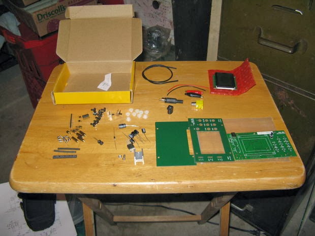
When your DSO 062 Oscilloscope arrives in the mail open it, inside you will find several packages of parts and two pieces of paper marked, “General Assembly Guide and 062 Oscilloscope Quick Reference”. Put everything back in the box but the paper marked “062 Oscilloscope Quick Reference”.

Take the quick reference to your computer, on the bottom of the quick reference it says “For Complete and updated documents please visit: http://www.jyetech.com that is JYETECH.

On your computer go to:
http://www.jyetech.com

Click on English

Under Quick Links Click on Documents

Down load all the files under models 06203P, 06203KP, and 06204KP for all three models it is the same files.

Quick Reference
Operating Instructions
Assembly Notes
Troubleshooting Guide
Assembly Back
Assembly Front
How to Upgrade Firmware by Bootloader
How to Program 062 Oscilloscopes
Part list
Schematic

Step 2: Print Files


Print the pdf files:

Assembly Notes
Troubleshooting Guide
Assembly Front
Assembly Back
Part list
Operating Instructions

The reason for printing the pdf files is so you can tick off the steppes as you follow the assembly notes.

Step 3: Check the Parts


From the printed pdf files check the parts make sure all the parts are in the kit and check them to be sure they fit the circuit board. Whether deliberately or by accident it is not uncommon for parts to be substituted in kits, so make sure they are the right parts and they fit before you start to assemble your oscilloscope.

Step 4: Tools


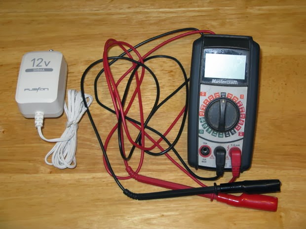
If all the parts are in the kit and they fit in place you will need these tools to assemble the oscilloscope. Power supply 9 to 12 volts DC 300 ma Multimeter Soldering iron Side cutters Wire striper Needle nose pliers Phillips screwdriver Solder

Step 5: Assembling the Oscilloscope 


Take your time and follow the step by step instructions of the assembly notes, the only thing I would add to them is use the long spacers to hold the circuit board up from your work table. Cut off the excess leads off the through hole parts as you add them to the circuit board or it will be like trying to solder through a hair brush. Your joint is good on the through hole parts if you can pluck the end of the excess wire lead and it rings like a guitar string.

Step 6: Testing 

 After assembling the circuit board completely you need to test the oscilloscope before putting the front and back plates on. Connect the power to the oscilloscope. The LCD should light up. “Boot loader” then should come on the LCD. The LCD should switch to WWW.JYETECH.COM. Last F= and Hz This indicates the oscilloscope is functioning normally, if it doesn’t display this on the LCD follow the Troubleshooting Guide.


Step 7: Assembling the Probe 


Strangely the assembly notes don’t tell you how to put the probe together, so in this step I will. After the oscilloscope is completely assembled gather the parts for the probe. Strip ¼ inch of the insolation off both ends of the small red and black wires and solder one end onto the alligator clips. Slip the rubber boots on to the alligator clips and slip the small shrink tube on to the wires. Next strip ½ inch of the insolation off the outside layer of the coaxial cable. Twist the outer braded wire. Strip ¼ inch of the insolation off the inner wire. Solder the red wire to the inner wire and the black wire to the outer braded wire. Slip the shrink tube over the joints and heat to shrink then slip the larger shrink tube over the two joints and heat to shrink.

Step 8: The BNC Connector 


Slip the BNC connectors collar over the coaxial cable and strip the end as before. Solder the center wire to the center tab of the BNC connector and the outer braded to the outer tab of the BNC connector. Then screw the collar back on the connector.

Step 9: Testing the Probe and Oscilloscope


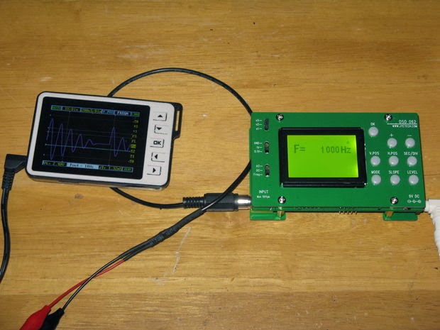
To test the probe and oscilloscope I connected the probe to the built in signal generator of my DSO Nano oscilloscope. Now when I power up the oscilloscope it said F= 1000Hz after booting up. Then I checked the other functions of the oscilloscope.

Step 10: Making a Portable Power Supply


 All the parts for this I got at my local Radio Shack the Source here in Canada. 8 AA batteries 1 9 volt battery terminal 1 coaxial power plug 1 12 volt AA battery holder Shrink tube Slip the shrink tube over the wires of the 9 volt battery terminal and heat to shrink. Unscrew the collar of the coaxial power plug and slip it over the wire of the 9 volt battery terminal. Then solder the red wire to the center tab of the coaxial cable connector and the black wire to the outer tab and screw the collar back in place. Place the 8 AA batteries in the battery holder, clip the 9 volt battery terminal to the holder, and plug it into the oscilloscope and watch it boot up.


 Step 11: And We Are Done